Custom cosmetic microneedle array design
Define the patterned area, skin-facing orientation and sample deliverable for a bespoke dissolving cosmetic microneedle patch.

Specify the surface you need. Compare raised masters, cavity molds and replicated arrays before sending a drawing for review.
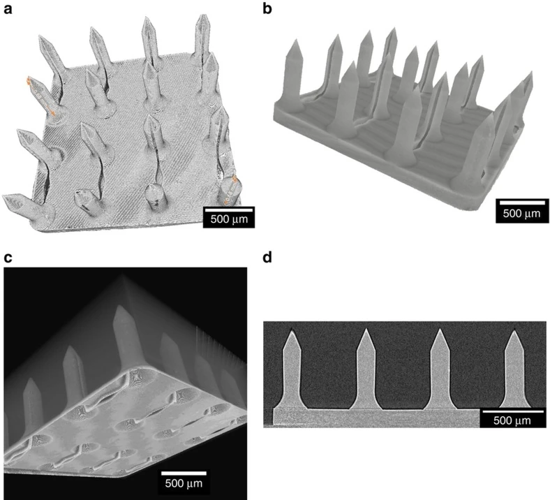
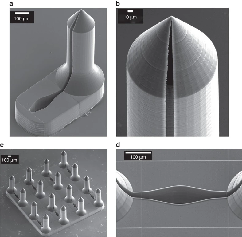
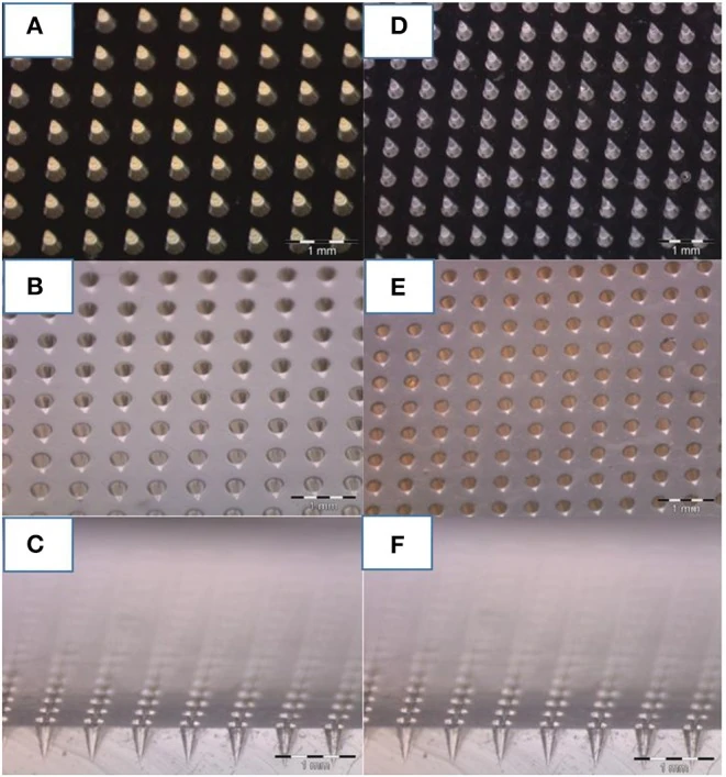
Define the patterned area, skin-facing orientation and sample deliverable for a bespoke dissolving cosmetic microneedle patch.
Identify a raised master, distinguish it from a finished cosmetic patch and request the right reference views for a tooling quotation.
Compare a recessed microneedle template with its positive counterpart and specify the working face for a mold sample.
Read a layout drawing by separating centre-to-centre pitch, row count, patterned footprint and the patch perimeter.
Compare common microneedle tip geometries from a supplier drawing and read what a profile view can actually establish.
Specify the material of each tooling component and distinguish it from the material declared for the finished cosmetic patch.
Show the die-cut perimeter and patterned needle field separately on cosmetic patch CAD drawings and sampling briefs.
Identify the removable liner, adhesive backing, protective tray and actual mold when describing a cosmetic patch sample.
Prepare a dimensioned patch drawing, orient the working face and agree on a revision for quoting, samples and inspection.
Request microscope views that connect a local detail to the correct sample, field position and approved drawing.
Compare the master, negative cavity and replicated array to investigate a visible difference during a cosmetic tooling review.
Choose which questions a standard array can answer and when a dedicated geometry or fixture deserves a separate quotation.
Keep the approved master, sample revision and repeat-order scope connected when a buyer orders cosmetic patch tooling again.
Prepare an RFQ for an array drawing review, a positive master, a negative template or a matched cosmetic patch sample.
Use reference corners, face labels and an array position map to trace a feature across drawings and supplier inspection images.
Learn what a cavity section can establish, how to match the section plane to a position and which questions to bring back to the supplier.
Match summary values to measured positions and compare edges, corners and center fields across supplier sample reports.
Separate surface texture observations from dimensional form when reviewing master tooling inspection reports and photographs.
Build a first-article file linking a delivered tool, a representative sample and itemized inspection evidence to the approved drawing.
No matching guides. Try a different word.