
Locate the slice on a plan view
A cavity section becomes easier to interpret once you know where the slice passes. Evens and colleagues showed sectioned views of tooling cavities in their study. For a buyer’s evidence request, mark the chosen position on the array overview and draw the proposed section line through it. Ask which image shows the opening and which shows the cavity interior. This lets a second reviewer establish that the two images refer to the same object.
Evens et al. (2022) · Cavity inspection and feature uniformity in molded arrays
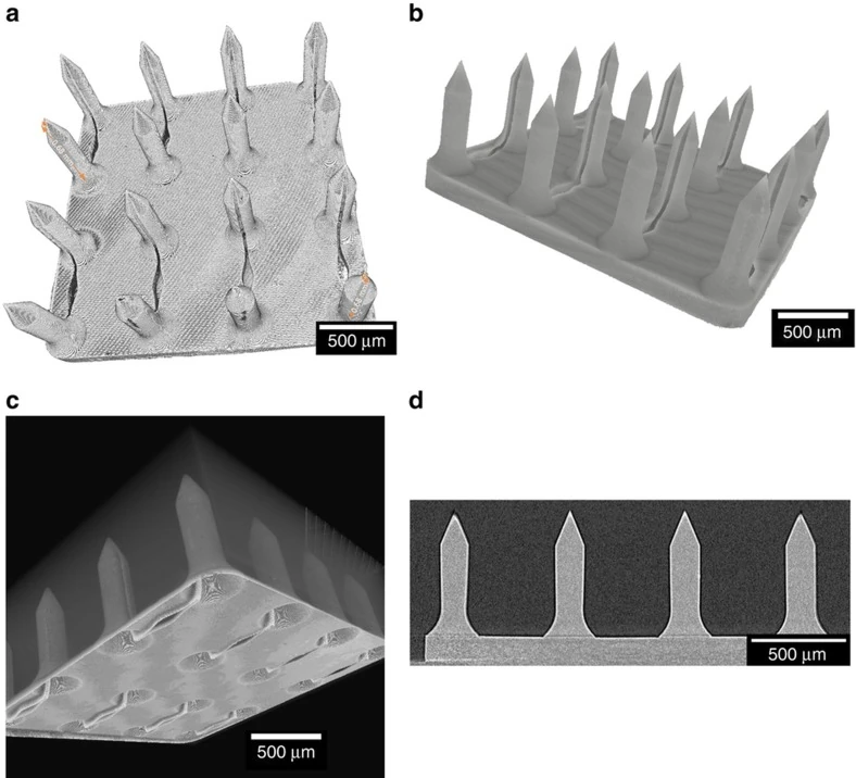
Image credits
Zahra Faraji Rad, Robert E Nordon, Carl J Anthony, Lynne Bilston, Philip D Prewett, Ji-Youn Arns, Christoph H Arns, Liangchi Zhang and Graham J Davies · Image source · CC BY 4.0 · Original figure proportions and markings retained; converted to WebP.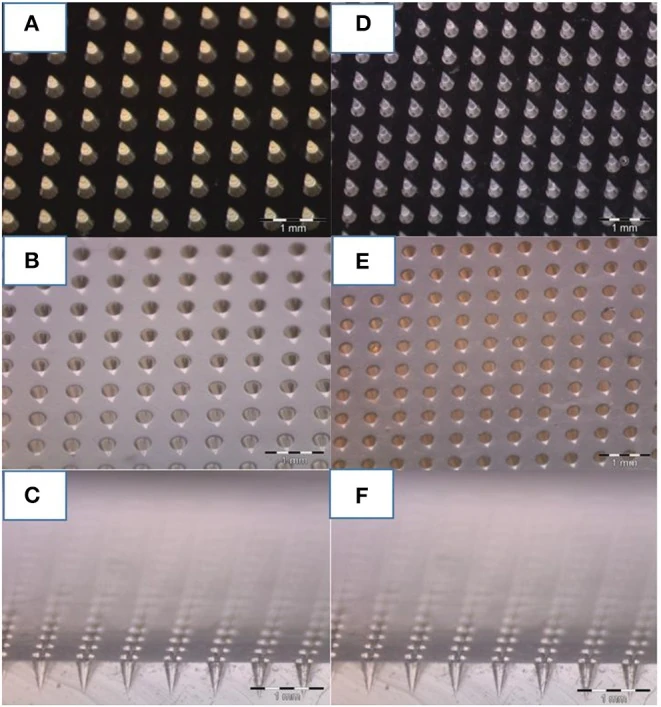
Image credits
Mario Battisti, Raffaele Vecchione, Costantino Casale, Fabrizio A Pennacchio, Vincenzo Lettera, Rezvan Jamaledin, Martina Profeta, Concetta Di Natale, Giorgia Imparato, Francesco Urciuolo and Paolo Antonio Netti · Image source · CC BY 4.0 · Original figure proportions and markings retained; converted to WebP.Compare sections taken through matching features
Faraji Rad and colleagues used three-dimensional imaging to compare a master, negative mold and molded replica. Imagine that a supplier sends a centered section of a master next to an off-center slice through the corresponding cavity. The outlines may look different even for closely corresponding features. Before recording a discrepancy, request the section locations, a scale and the reference surface used for depth. If the information is unavailable, leave the comparison open.
Faraji Rad et al. (2017) · Three-dimensional comparison of master, mold and replica
Report what the evidence can resolve
Evens and colleagues illustrated an empty cavity and a cavity holding a broken feature. In a commercial dispute, ask the reviewer to describe the visible condition and identify the corresponding sample or tool. An image may establish that material is visible while leaving its identity or origin uncertain. Write down which question remains, whether an additional image would settle it and who holds the original file. This keeps the follow-up focused and reviewable.
Evens et al. (2022) · Cavity inspection and feature uniformity in molded arrays
Prepare your inquiry
Register the section line and cavity position before drawing conclusions from the profile.