
Draw three boundaries
A crescent may have an outer cut edge, an adhesive border and a smaller patterned field. Show the boundaries in separate layers or with clearly named line styles. A single outline sent by email leaves the tooling vendor to guess how much of the shape carries features.
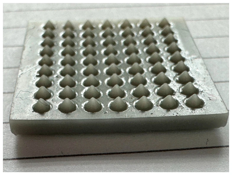
Image credits
Faisal Khaled Aldawood, Abhay Andar and Salil Desai · Image source · CC BY 4.0 · Original figure proportions and markings retained; converted to WebP.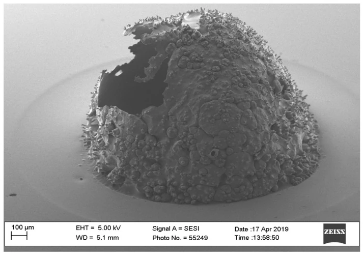
Image credits
Faisal Khaled Aldawood, Abhay Andar and Salil Desai · Image source · CC BY 4.0 · Original figure proportions and markings retained; converted to WebP.Compare left and right pieces
Under-eye patches may be supplied in mirrored pairs. Identify a stable orientation mark and show the same viewing side for both drawings. On a sample carrier, write down whether the pieces are presented skin-facing up or down so the field position can be compared consistently.
Separate a tool change from a die change
A request to widen the smooth margin might move the field, the cut edge or both. Circle the intended change on the overlay. Ask which components are affected before authorizing new tooling or revising the sample specification.
Can a buyer verify the field location against the finished outline?
The research layouts shown by La Malfa and colleagues distinguish individual feature fields and use a positional reference. For an eye-shaped cosmetic patch, define a comparable reference on the outline drawing, such as the end facing the nose. Ask for the field boundary in that same view and a marked photograph of the assembly for orientation. A separate dimension for the distance between field and outline helps a buyer compare two samples that appear almost identical at first glance.
La Malfa et al. (2025) · Reference features and coded arrays in mold replication
Prepare your inquiry
Show the cut line, adhesive boundary and needle field separately.