
Give units and orientation their own space
Include the date, part identifier, drawing revision, units and viewing side on the same sheet as the geometry. If the outer outline and working field are shown at different scales, label both. A screenshot of a CAD window rarely preserves enough context to resolve a disagreement later.
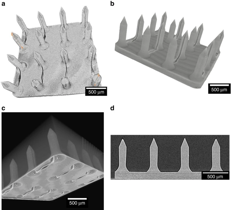
Image credits
Zahra Faraji Rad, Robert E Nordon, Carl J Anthony, Lynne Bilston, Philip D Prewett, Ji-Youn Arns, Christoph H Arns, Liangchi Zhang and Graham J Davies · Image source · CC BY 4.0 · Original figure proportions and markings retained; converted to WebP.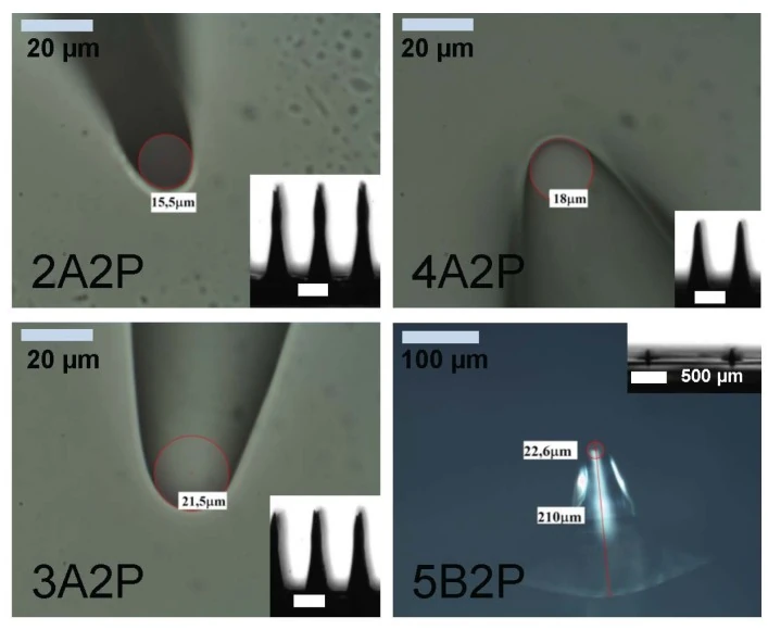
Image credits
Principia Dardano, Alessandro Caliò, Vincenza Di Palma, Maria Fortuna Bevilacqua, Andrea Di Matteo and Luca De Stefano · Image source · CC BY 4.0 · Original figure proportions and markings retained; converted to WebP.Resolve conflicting references
A neutral 3D file and a dimensioned PDF serve different readers. If a quoted dimension conflicts with the model or with a hand-marked sample image, ask which file controls that feature. Record the answer and issue a revised file if necessary.
Make the response easy to approve
Ask the reviewer to return an annotated copy that distinguishes an accepted dimension from a question or proposed change. Date the accepted drawing and send that revision to purchasing alongside the sample request. Archive earlier revisions under their own identifiers.
Where do the drawing dimension and the measured dimension start?
Faraji Rad and colleagues set out nominal and measured dimensions for several tooling stages. When reviewing a CAD export, select a dimension and trace its two endpoints through the drawing and the inspection image. A feature height referenced to the local base and a height referenced to the underside of its support use different starting surfaces. Mark the agreed surface on an annotated section, and ask the reviewer to use its label in the returned measurement sheet.
Faraji Rad et al. (2017) · Three-dimensional comparison of master, mold and replica
Prepare your inquiry
Send a dated model and readable drawing with clear precedence.