Microneedle pitch, spacing and array footprint
Read a layout drawing by separating centre-to-centre pitch, row count, patterned footprint and the patch perimeter.

Read a layout drawing by separating centre-to-centre pitch, row count, patterned footprint and the patch perimeter.
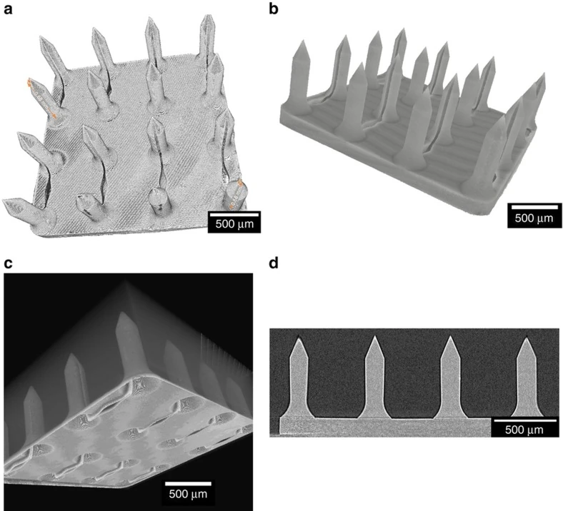
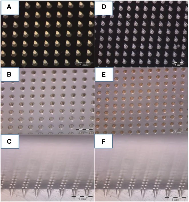
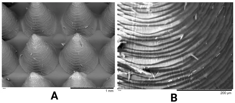
Read a layout drawing by separating centre-to-centre pitch, row count, patterned footprint and the patch perimeter.
Compare common microneedle tip geometries from a supplier drawing and read what a profile view can actually establish.
Show the die-cut perimeter and patterned needle field separately on cosmetic patch CAD drawings and sampling briefs.
Identify the removable liner, adhesive backing, protective tray and actual mold when describing a cosmetic patch sample.
Prepare a dimensioned patch drawing, orient the working face and agree on a revision for quoting, samples and inspection.
Use reference corners, face labels and an array position map to trace a feature across drawings and supplier inspection images.
No matching guides. Try a different word.